
Overview
- Display driver testing on BlackPill and BluePill boards
- LVGL integration and performance testing with BlackPill
- First tests of our display with our Nordic development kit
Welcome to our Second Behind the Scenes Article!
This will include all of our early testing with various development boards and testing our LCD with our own drivers and with LVGL. This will be a jam-packed update so grab a snack, get comfortable, and let's dive right in!
Our First Real Display Tests
In our last update, we showed how we got our LCD to work with QMK’s Quantum Painter API, but in this update, we will be exploring different ways to use the display without it because we decided to use ZMK instead.
The first tests were with the Glyf prototype we previously used with QMK. Instead of using QMK though, we are testing by programming without any keyboard firmware as a base and are coding it from the ground up. Because this prototype uses an STM microcontroller, we had to learn STM32CubeIDE from scratch. Using this IDE had a bit of a learning curve because I hadn’t programmed this close to the hardware before. Thankfully there are good resources online to help learn how everything works.
We were hoping to go straight to testing with LVGL on this build, but after learning how to port LVGL (which I will talk about later) and getting everything set up, we learned that the microcontroller we used on this board didn’t have enough flash memory or ram to even flash the program, even with all of the configuration options turned off. I thought that we would have had enough resources to run just LVGL by itself without the added firmware size of QMK, but it turned out to not be the case. I could have tried to strip down LVGL to bare bones to get it to work on this build, but at that point, it would defeat the purpose of using it. As a result, we pivoted to try some display tests with basic display drivers just to see how the screen would look. I was able to find some example ST7735 driver code on GitHub that I was able to modify and get working. After adding some code to test the driver’s capabilities, this is what it looked like:
The first thing we noticed was how slow drawing to the screen was, after some tweaks, we were able to get it a bit faster and this was the result:
This was the extent of the testing we could do on this board because of the microcontroller's hardware limitations.
Hello BluePill
At this point, because we had the BluePill on hand from using it as a programmer/debugger, we decided to give it a shot to see how it would perform. Testing the display drivers here was as simple as changing a few lines of code and bam, we got our second working board.
This was already much faster than our previous tests because the clock speed on this board is much higher, making drawing to the screen way smoother. From here, we did some more basic driver tests like writing text, controlling the screen with user input, and more. My favorite example while messing around with this build (although not 100% applicable to Glyf) was getting our LCD and a servo motor to react to the position of a potentiometer.
Even with all the improvements this board offers, it still didn’t have enough power for what we were looking for. We decided to get another, very similar STM board to continue testing with better performance.
Goodbye BluePill, Hello BlackPill
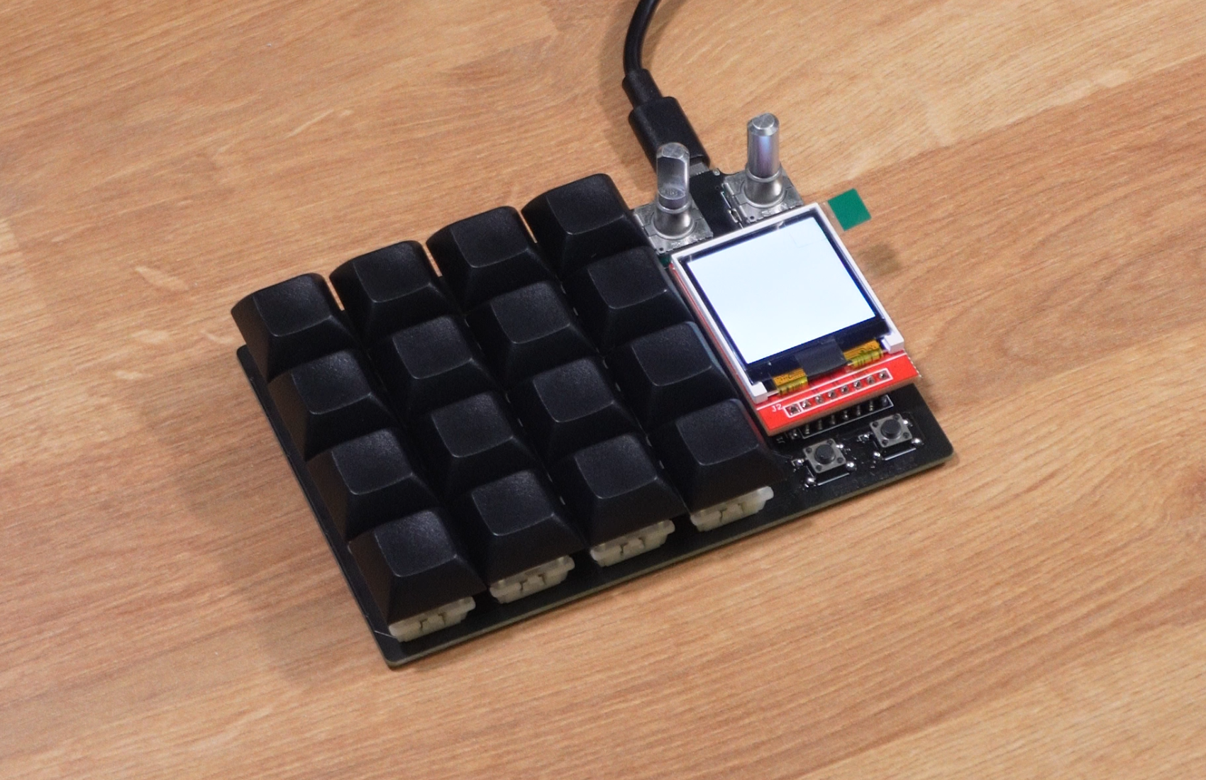
The BlackPill is quite a substantial improvement from the BluePill in terms of raw specs – more flash, more RAM, faster clock – and it is exactly what we need to continue our testing. The faster display update speed is apparent with the first test we did using base drivers.
We now have enough power to test out LVGL. Here begins the long and painful grind of getting it to work correctly. Compared to getting the LCD to work with a simple driver, this part was much harder and required me to learn a lot more about how LCDs are driven over SPI and how displays work in general.
One of the reasons this part was more difficult was because there are multiple versions of LVGL we could have chosen. They had just released version 9.0 when I started to test it which had a lot of nice features above previous versions. There was one problem with using this version though, SquareLine Studio did not support this version yet. Squareline Studio is a UI editor that makes it easier to design with LVGL by providing code output based on drag-and-drop designing through their application. This would help us speed up creating the UI tremendously. Because of this, we decided to test with one of the version 8 snapshots of LVGL. In the version we chose, you have to implement your own display flush callback function among other things. This turned out to be more difficult than I thought because I didn’t know how LCDs even worked at a lower level at this point. I researched more into it and gained a base understanding of the concepts. I then attempted to modify the driver we used before and that was half successful. I was able to display LVGL widgets but they were pixelated and something was off. After many, many, attempts at converting code from the base driver to the display flush function, I decided to switch to LVGLv9.0. Even though this wouldn’t let us use Squareline Studio at the moment, using this version gives us access to in-tree drivers for our display. After some more attempts to try to get it to work, we finally got something!
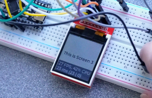
The next steps were to test LVGL slightly more in-depth. We created a sample program that cycles through screen layers.
After doing all this testing with both development boards, it gave us a good understanding of how we will be able to use the LCD with Glyf. Because Glyf will have Bluetooth, we are finally going to be testing with our Nordic development kit to make sure everything works correctly.
Goodbye BlackPill, Hello nRF52840DK
Finally, we get to test with a development kit that is closest to what Glyf will actually be. Just like in our first update article, this involved a lot of research into Zephyr and ZMK, but it additionally required research into NRF Connect. We considered using Zephyr on its own, but since the NRF Connect SDK is necessary to make the board functional without using 3rd party drivers, we decided to integrate both from the start.
Inside the NRF Connect SDK, we have access to Zephyr sample code. To test how the screen works with this code, all we need to do is set the correct device tree configuration and have the Zephyr display device point to our LCD configuration. This was more annoying than it should have been because right when I was testing this, the internal Zephyr implementation for certain display drivers was being moved to mipi-dbi. This is fine, but the only problem was that the version of Zephyr inside of NRF Connect SDK was not fully up to date with all these changes. This is something I found out after lots of headache and painful testing - it was a good lesson to learn though. After getting the versioning sorted, this is the first display test with our dev kit:
It still looks slightly off, but I’m just going to say that is a driver issue 😛 It doesn’t matter that much if this one is perfect because it is not the final LCD we are going to use.
Finally, ZMK!
I’ll end things off by showing ZMK working on our development board. To keep things short and sweet, after a LOT of testing, learning GitHub Actions, refreshing my Docker knowledge, and much more, I was able to create a local environment for ZMK, create an overlay appropriate for our dev kit, and get the first version of ZMK working on it. If you look closely at the video, you can see we are typing the letter ‘a’ in the terminal over Bluetooth.
FIN
That’s all for this update, thanks for reading to the end! Keep looking out for more updates as we will have more coming your way.
Noah
3 comments
Owen Grant
hey, i’m interested in your products and what you plan to make in the future, check out the smart knob on youtube it’s by scottbez1, let’s just say, if you were to make and sell this, or something equivalent, i’d buy it immediately, highly suggest you looking into making one of them, and perhaps making like a board that has multiple with, you guessed it, more keys at the bottom, lol, anyway love your stuff, look forward to hopefully hearing back from you?
thanks,
Owen
Lance Terrill
Lovely work! Can’t wait to see it in full action!
a
a
Leave a comment
This site is protected by hCaptcha and the hCaptcha Privacy Policy and Terms of Service apply.