
Overview
- Built two Glyf prototypes with knobs, LCD, and Bluetooth
- Switched from QMK to ZMK for better Bluetooth support
- Tested LCD displays and optimized Bluetooth performance
- Overcame bootloader and ZMK learning challenges
Welcome to our First Behind the Scenes Article!
In this article, we will show you what we have been working on at Prota Designs. We have been busy at work designing and creating some new stuff for you and decided we want to share our journey in more detail for those who want a more in-depth look at our process.
Initial Development of Glyf
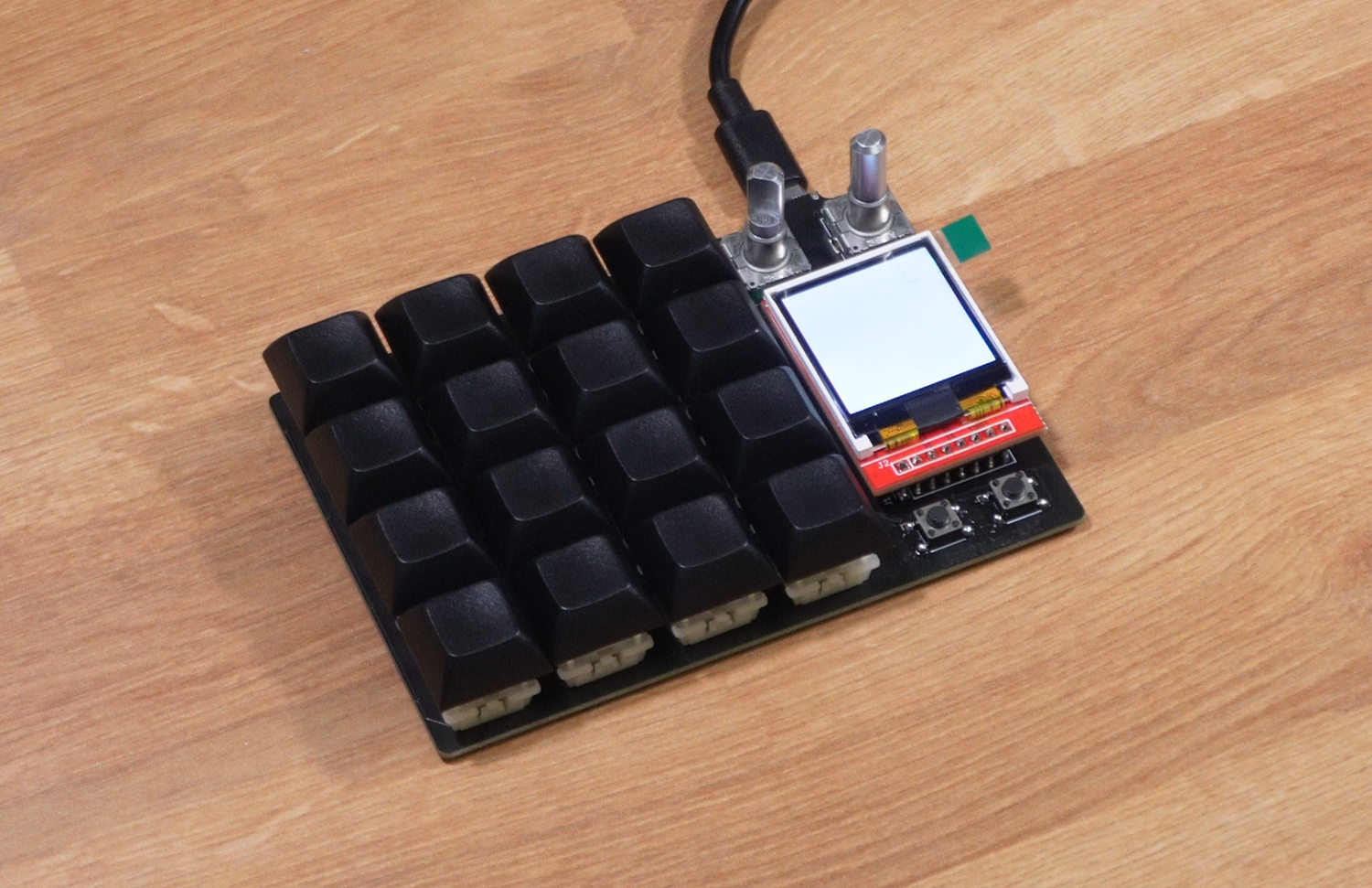
In the beginning… we made the first PCB based off the same hardware the Printed Pad uses and added two knobs, a screen, two buttons to control the screen, and more keys!


This prototype was a rough proof of concept to test the spacing, how we liked the form factor, and how the user interface worked with VIA for now. Check out the video below!
Now I will pass it off to Noah to discuss how we began testing this new design.
Firmware Testing
Because our first prototype is based on the Printed Pad, we already have the base code figured out and can start working on getting the new components to work. This first build uses QMK firmware which is optimized for fully wired builds, fitting the requirements of our first prototype.
The first addition that we tested was the rotary encoders. This was relatively simple to implement because there are already many example keyboards that we can use as a reference and the QMK documentation provides a good explanation of how they work. Even with this one base addition, we found it adds so much value to our productivity with our initial testing.
The next, and more flashy addition we tested was the added LCD screen. This was more work to test because the OLED on the Printed Pad uses I2C and the new LCD uses SPI. Our first plan was to use LVGL (an easy to use graphics library made for embedded systems) but unfortunately, our first prototype didn’t have enough memory to run all of the base firmware in addition to LVGL, even with all of the optional includes turned off. The limited internal flash storage in the MCU we used for the Printed Pad wasn’t an issue because we only had to store the keyboard firmware and user keymaps on it, but it is an issue when we have to store images, animations, and other UI in addition to our graphics library. Changing our plans to still make use of the LCD in this build, we pivoted to using Quantum Painter which is a standardized API made for displays that is built into QMK. This isn’t the best to use for complex display UI, but it will let us test how the keyboard firmware will interact with a more dynamic display compared to the Printed Pad. After adding the proper configuration to the firmware for SPI and our display drivers, it worked like a charm.

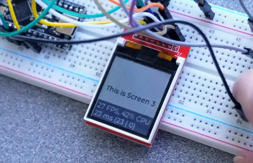
Our first tests were to try and display any image to see how it works. This required learning about display buffers and how images should be loaded into memory to be displayed. Although the Quantum Painter API makes this easy to do, we went more in depth into researching this because it will be important for LVGL in the future. After some adjustments to settings such as the offset of the screen and color settings, we were able to get it looking pretty good. Now that we know the display works, the next step was to add interactions between the screen and different layer states. Because we aren’t using LVGL for this build, we opted to just show a number on the screen for each of the 4 layers.
This ended up working as well. With these two display tests, we learned a lot about how our new LCD works with things like displaying images, image quality, effect of the backlight, screen timeouts, and more. It also solidified the completion of the first working prototype for Glyf.
Next up, Bluetooth
After the initial success of the first prototype for Glyf, the next challenge is to integrate Bluetooth. This part is more complex than it sounds because it requires optimizing for things such as power consumption and latency. Because this is an important feature for Glyf to get right, we decided to make some big changes in the platform we are building it on. The Printed Pad uses QMK firmware as its base but we decided to move Glyf to use ZMK firmware. This change was not taken lightly because it is a whole new platform we didn’t have experience with. We made this change because ZMK firmware is optimized for Bluetooth microcontrollers and will serve as a better base as we expand functionality for Glyf.
I will pass it back to Ben to explain what changes he made to the design for our updated second prototype.
Bluetooth Design Considerations
When it comes to Bluetooth, there are a lot of design considerations like power consumption, a battery management system, a real-time clock, and more. There were a lot of new schematics we had to learn about to make it all possible and lots of data sheets to read to make sure each component is able to work with one another. Specifically, some of the biggest changes we made was adding memory, a battery management system, an on and off switch, a GPIO expander, and pull up resistors. The battery management handles power coming in from the USB-C to charge the battery, the temperature of the battery, and the power supply coming out of the battery to power the whole system when in Bluetooth mode. Here is a glimpse of the bird nest I had to wire together…


Once I was able to verify that everything was wired up correctly, I hit the buy now button and didn’t give it a second thought until the prototypes came in the mail :)
Back to Noah to talk about testing our second prototype.
Testing Bluetooth Prototype
Testing our second prototype was substantially more challenging than testing the first. The platform shift required learning about a whole different development ecosystem. During this stage, ZMK documentation and their discord server were immensely helpful in filling in my knowledge. Although I am pretty familiar with QMK, ZMK feels quite different in how they structure their files and how everything interacts. ZMK uses Zephyr RTOS which uses Kconfig and devicetree files (both based on Linux kernel files) which were a challenge to learn at the beginning. After learning them, it does make development easier though, because they allow for device abstraction and code isolation. Device tree files are for hardware definitions so it is easy to identify and configure their base functionality. Kconfig files are for system configuration where you define options for various features, system behavior, and peripheral settings. This separation of concerns is nice to work with because it makes code more organized and easier to modify.

Another challenge with using this prototype was loading code onto it. The Printed Pad uses an MCU that has a bootloader (a small program that allows the device to receive and load application code) on it from the factory, but the Nordic microcontroller we chose for Glyf doesn’t have a preinstalled bootloader. A bootloader lets us program the board without using an external programmer. If we want to do this, we need to install one ourselves. To get a bootloader onto the board, we need to use an external programmer, the one we chose was a Bluepill microcontroller flashed as a Blackmagic probe. After lots and lots of debugging and troubleshooting, we were able to get a bootloader onto the board.

Stay tuned for more😋
- Ben and Noah
1 comment
John
Interesting. Why are you using windows and power shell though, That’s so wierd
Leave a comment
This site is protected by hCaptcha and the hCaptcha Privacy Policy and Terms of Service apply.